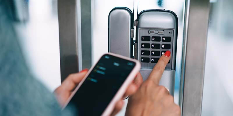
Smart electronic locks are widely used commodities in the field of smart homes. And personalized voice interaction is one of the important manifestations of the intelligentization of electronic locks. In the field of electronic locks, the Voice Chip WT588F02B-8S of Waytronic has been favored by many electronic lock brands.
Ordinary smart electronic locks need voice interaction function and clock function. It is necessary to realize the intelligence of the electronic lock through MCU + voice chip + clock chip and other components. There are many personalized devices, which means that the circuit design is relatively complicated, the circuit board is bulky, and the cost is high.
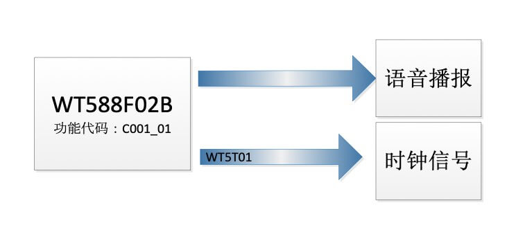
The WT588F02B-8S electronic smart lock solution only needs to rely on a WT588F02B-8S voice chip to solve the two functions of voice broadcast + clock, which greatly saves product development costs, reduces the number of circuit components, and simplifies the circuit. Product development is more convenient.
components, and simplifies the circuit. Product development is more convenient.
One system composition
#1 WT588F02B-8S chip parameters are as follows
- 16-bit DSP voice chip, 32Mhz internal oscillation;
- Working voltage 2.0-5.5V
- The 16bit PWM/DAC output can directly drive 8R 0.5W speakers;
- Support 6K~32Khz WAV files;
- After the chip playing is over, and the IO ports (DATA and CLK) maintain a stable level (both high and low levels) for 1 second, the chip enters sleep
#2 02B special function description:
- Customers can change the internal voice content of the chip online through MCU or supporting downloader;
- Support 224 segment addresses, which can be expanded with more requirements;
#3 WT5T01 second chip jump
- Provide second jump signal to WT588F02B-8S
#4 Other peripherals
- Press the key;
- Digital tube and LED;
- Internal power supply CR1220, external power supply 5V power supply or 3 AA batteries.
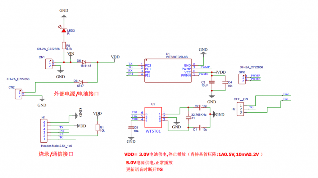
Two circuit design
#1 Circuit schematic diagram
#2 Device selection
| Part | Part number | Features overview |
| Master chip | WT588F02B | 16-bit DSP, 32MHz, 256KB-flash, re-erasable |
| Clock IC | WT5T01 | jump in seconds |
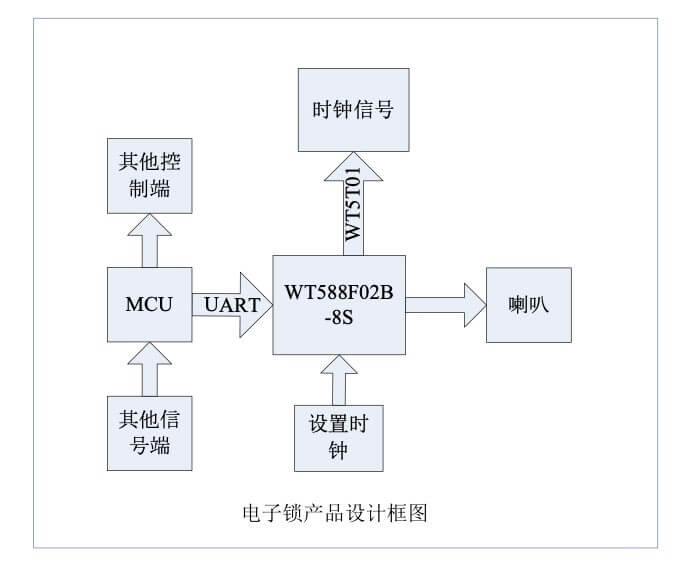
#3 Application framework diagram
#4 control methods
Use touch buttons and second jump chip control. Touching the button to control the smart door lock can also trigger the voice IC to broadcast the voice at the same time. The function of the clock is set to have the record of unlocking the lock.
Setting the clock: You can send commands to the WT588F02B-8S chip to set the clock through Uart serial communication. Another solution is to add a light sensor to the entire system and use the light sensor and APP to set the clock information.